
Chip Harness, Part 2: The Design Loop
28 Sep 2026In Part 1 I gave the big picture of the harness I built at the MongoDB hackathon. This post goes one level down into the design loop: the part where AI agents actually edit hardware, and where every idea gets checked against real place-and-route results.
The code is at github.com/chmartin/chip-harness. All the snippets below are from the version that ran on the day.
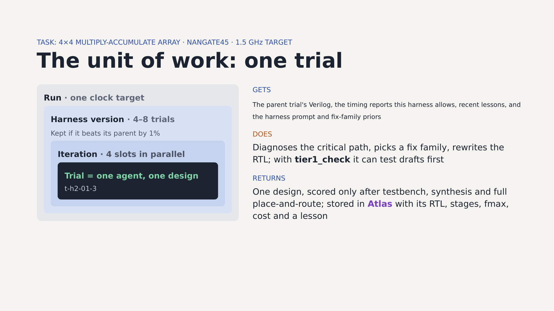 The unit of work. A run has one clock target. Each harness version gets 4–8 trials. Each iteration runs 4 agents in parallel, and each trial is one agent producing one design.
The design under test
The test block is a 4×4 array of signed 4-bit multiply-accumulate (MAC) units, each with a 24-bit accumulator, plus a registered output mux that selects one accumulator. Here is the core of the baseline:
wire signed [7:0] p = a * b;
reg  signed [ACC-1:0] acc;
always @(posedge clk or negedge rst_n)
  if (!rst_n)      acc <= 0;
  else if (clear)  acc <= 0;
  else if (en)     acc <= acc + {{(ACC-8){p[7]}}, p};
In one clock cycle the signal has to go through a multiplier, a sign extension and a 24-bit adder, and land back in the accumulator register. That long combinational chain is what limits the clock. It’s small enough to place and route in about five minutes on a laptop, but it has a real design trap in it, which will matter later: the accumulator is a feedback loop.
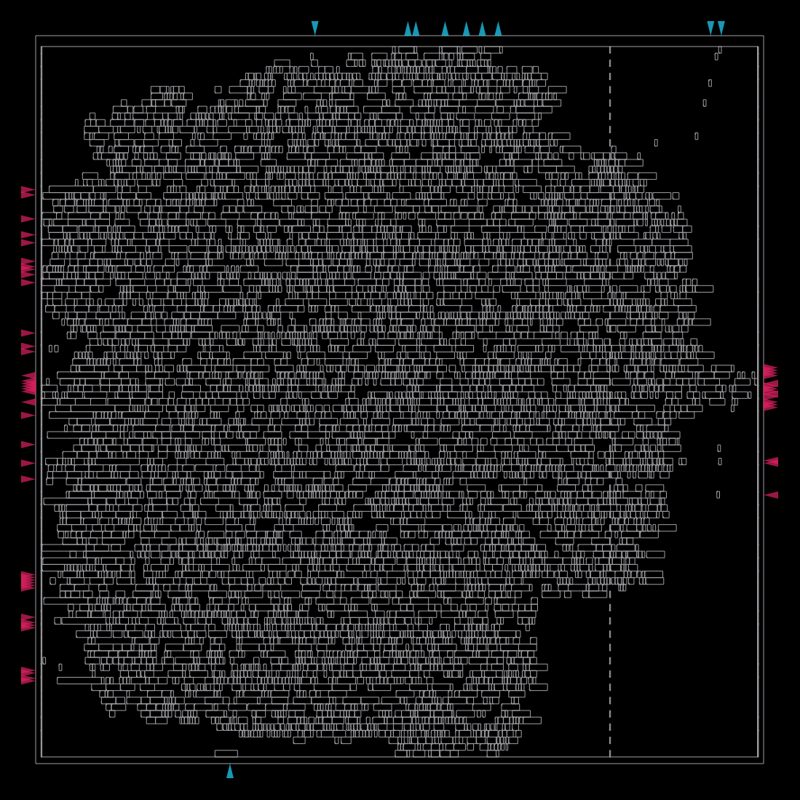
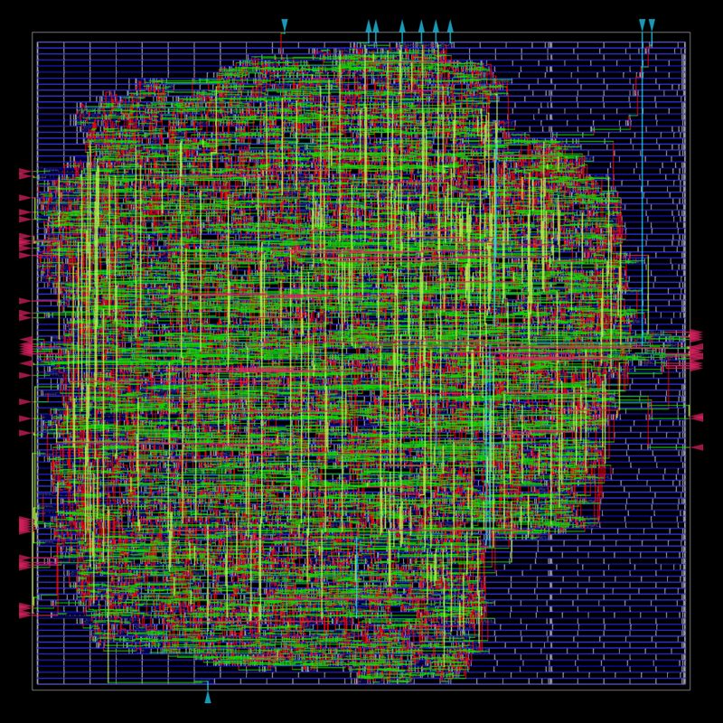
This is what the baseline looks like after OpenROAD is done with it. Every design in this post goes all the way to a routed layout like this before it gets a score.
The rules the agents must follow
The agents can rewrite the module’s internals however they like, but a few things are fixed, and a testbench checks them:
- The module name, parameters and ports stay exactly as they are.
outmust equal the selected accumulator, but up to 5 extra cycles of latency are allowed on the accumulate path and on the select-to-output path. This is what makes pipelining legal.- Accumulators wrap at 24 bits,
clearzeroes them and reset zeroes everything. - It has to be plain, synthesizable Verilog-2005.
The testbench compares the design against a reference model, using random operands and a random en in every lane over 2,100 cycles. It’s deliberately hard to pass by accident.
The score: routed silicon, not an estimate
A design’s score is its maximum clock frequency after full place-and-route:
fmax (MHz) = 1000 / (clock period − worst setup slack)
A design only counts as valid if it passes the testbench, the flow completes, and there are zero design-rule (DRC) violations. There is no LLM judging anything. If the wires don’t close timing, the number says so.
Tiered evaluation
Place-and-route is the expensive part, so each candidate goes through a series of gates, cheapest first:
| Stage | Tool | Time | What it catches |
|---|---|---|---|
| Testbench | iverilog | seconds | Functionally broken designs |
| Tier 1 | Yosys + ABC on Nangate45 | seconds | Designs that don’t synthesize; a rough timing estimate |
| Tier 2 | OpenROAD-flow-scripts (Docker) | ~5 min | The real score: fmax, area, DRC |
Tier 1’s timing estimate is pessimistic by about 1.5 ns, so it’s never used as a score. The harness can use it relative to the parent design to skip place-and-route for candidates that clearly got worse. That’s a policy knob the evolution loop is allowed to turn, which I’ll cover in Part 3.
The place-and-route setup is intentionally plain: Nangate45, 40% core utilization, 0.60 placement density, 0.1 ns I/O delays. On my M1 Max it runs the amd64 OpenROAD image under Rosetta (with the logic-equivalence check turned off), four designs in parallel, at about 8.4 CPU-minutes each.
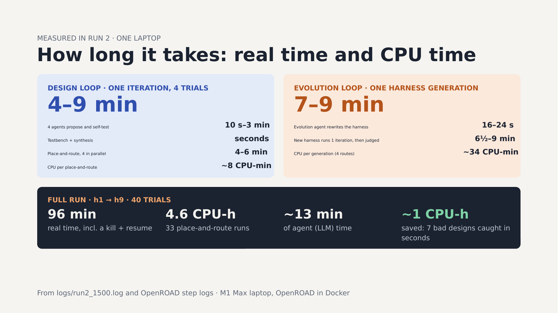 Where the time goes, measured in run 2 on one laptop.
In run 2 the testbench gate rejected 7 broken designs within seconds. Running them through place-and-route would have cost about a CPU-hour.
The design agent
Each iteration launches four design agents in parallel (Strands Agents, with Claude Sonnet 4.5 via OpenRouter). What each one sees and can do is not hard-coded. It’s read from the current harness version’s config:
- Reports: only the summary slack, or also the critical-path report from OpenROAD, or the Yosys stats.
- Lessons: 0–8 notes from earlier trials (“this helped / this hurt, and here’s the testbench error”).
- Fix family: each agent is assigned one family (
pipeline_register,retiming,logic_restructure, and so on), sampled from weights in the config. The random seed comes from the version and iteration, so a resumed run reproduces the same assignments. - Tools: possibly none, or possibly
tier1_check.
The agent has to reply with a small JSON block (goal, fix family, what it thinks the bottleneck is) and the complete new module. That structure is what fills the trial history the evolution agent reads later.
The one tool is simple, and it turned out to matter more than anything else:
@tool
def tier1_check(verilog: str) -> str:
    """Run the testbench and a fast Yosys timing estimate on a draft of the
    full mac_array module. Use before your final answer."""
It lets an agent test its own draft before submitting it: run the testbench, and if the draft passes, compare the Tier 1 slack to the parent’s. The seed harness doesn’t include it. You’ll see why that matters next.
Anatomy of a failure
In run 1, the seed harness’s agents all reached for the textbook fix: register the multiplier output so the multiply and the add happen in different cycles. Here’s how one of them failed:
FAIL cell 5 got -108 want -120
FAIL cell 6 got -43 want -61
TB FAIL (64 errors / 96 checks)
The agent registered the product but didn’t delay en and clear to match. The accumulator was adding last cycle’s product under this cycle’s enable. It’s a classic pipelining bug, and it’s easy to miss when you’re only told a slack number.
Run 2 showed a subtler version of the same trap. The seed harness hit 1,529.8 MHz on its first try, then broke the design seven times in a row trying to “split the 24-bit accumulator adder into two stages”. You can pipeline the feed-forward path (the multiply and the sign extension) freely. You can’t naively add a register inside a feedback loop, because the next addition needs this cycle’s result.
Anatomy of a success
Here is the winning design from run 1 (1,332.2 MHz, up from 909.5), trimmed:
// control pipeline, delayed to match the data
always @(posedge clk or negedge rst_n)
  if (!rst_n) begin en_p <= 0; clear_p <= 0; en_pp <= 0; clear_pp <= 0; end
  else begin en_p <= en; clear_p <= clear; en_pp <= en_p; clear_pp <= clear_p; end

// per MAC unit
always @(posedge clk ...) p_p   <= a * b;                       // stage 1: multiply
always @(posedge clk ...) p_ext <= {{(ACC-8){p_p[7]}}, p_p};    // stage 2: sign-extend
always @(posedge clk ...)
  if (clear_pp) acc <= 0; else if (en_pp) acc <= acc + p_ext;   // stage 3: accumulate
It’s two feed-forward pipeline stages, with the control signals delayed by the same two cycles, and the accumulator loop left untouched. That’s simple, but it’s correct, and it’s exactly what the seed harness’s agents couldn’t produce without a way to test their drafts.
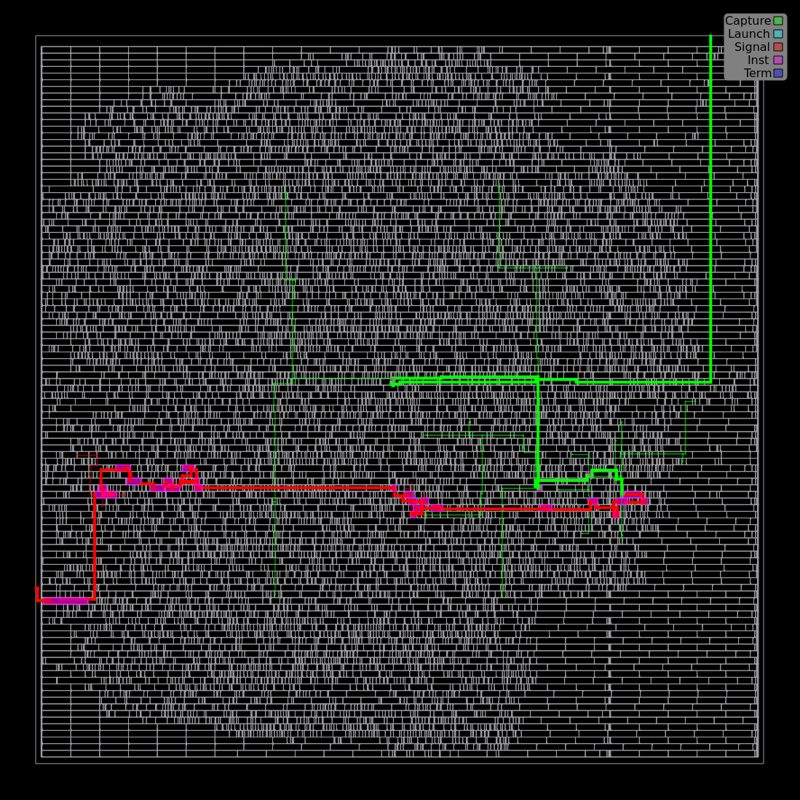
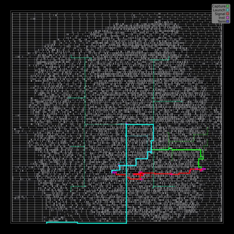
The same move carried run 2. Here is the worst timing path before and after (the highlighted path is the slowest route a signal takes in one clock cycle):
The loop itself
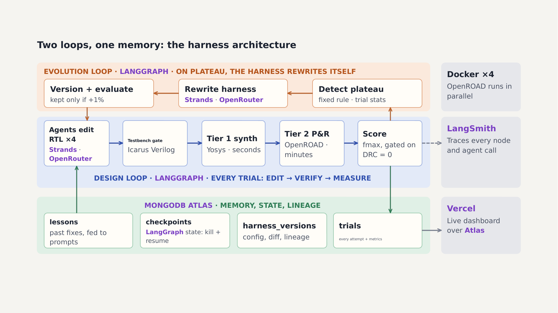 The design loop is the blue band. The evolution loop (orange) is Part 3.
The design loop is a LangGraph state graph:
pick_parent → propose ×4 → evaluate ×4 → check_plateau ─┬─► pick_parent
                                                          └─► evolve (Part 3)
- pick_parent takes the best valid trial so far as the starting point.
- propose runs the four agents in parallel.
- evaluate runs each candidate through the gates, writes a trial document and a lesson to MongoDB Atlas, and updates the version’s stats.
- check_plateau decides whether to keep going or hand off to the evolution loop.
Every trial has a deterministic ID such as t-h2-02-3 (harness version, iteration, slot), and LangGraph checkpoints its state to Atlas after every node. If I kill the run, --resume picks up at the same node, and trials that already finished are skipped instead of re-run. I did this live during run 2.
Each trial document holds the full RTL, every stage’s results, the agent’s stated goal and diagnosis, and its token usage. That’s what makes the evolution loop possible: it can read why designs failed, not just that they did.
Where the metric ran out
One limitation surprised me. Once a design meets the clock target, OpenROAD stops working hard to improve it, so every good design reports about the same slack. At a 1 GHz target, run 1 got stuck at about 1,332 MHz for exactly that reason. At 1.5 GHz, run 2’s valid designs all bunched between 1,520 and 1,545 MHz. The score was saturating, not the design.
The fix is to set a target the design can’t reach, or to score slack margin directly. That’s first on my list for the next run, along with bigger designs and exposing flow knobs (utilization, density) as things the agents can change.
Tools in this part
The full toolbox, with a note on each product, is in Part 1. The ones doing the work in the design loop:
- Icarus Verilog (open-source Verilog simulator): runs the testbench gate.
- Yosys + ABC (open-source synthesis and logic optimization): Tier 1’s seconds-long synthesis and timing estimate, and the
tier1_checktool. - OpenROAD-flow-scripts on Nangate45 (open-source RTL-to-layout flow and 45 nm cell library): Tier 2 place-and-route, the real score.
- Docker: runs the OpenROAD image, four jobs in parallel.
- Strands Agents (AWS’s open-source agent SDK) with Claude Sonnet 4.5 via OpenRouter: the four design agents and their tools.
- LangGraph: the loop’s nodes, parallel fan-out and checkpointing.
- MongoDB Atlas: a document per trial (RTL, stage results, goal, diagnosis, tokens) and a lesson per trial.
In Part 3 I’ll cover the other half: how the harness decides it’s stuck, and how it rewrites itself.